
Member Projects Photograph Album (1)
We hope you enjoy viewing this page of this photograph album of our model building efforts. By selecting a photograph, you will be able to view a slide show presentation for the particular group you selected.
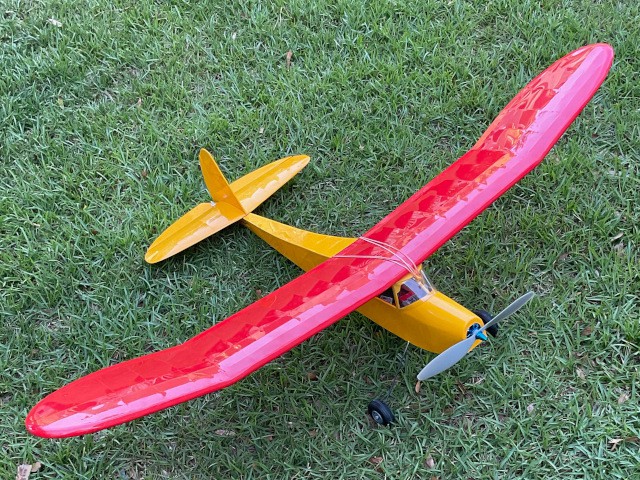
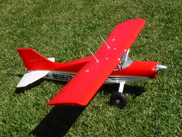
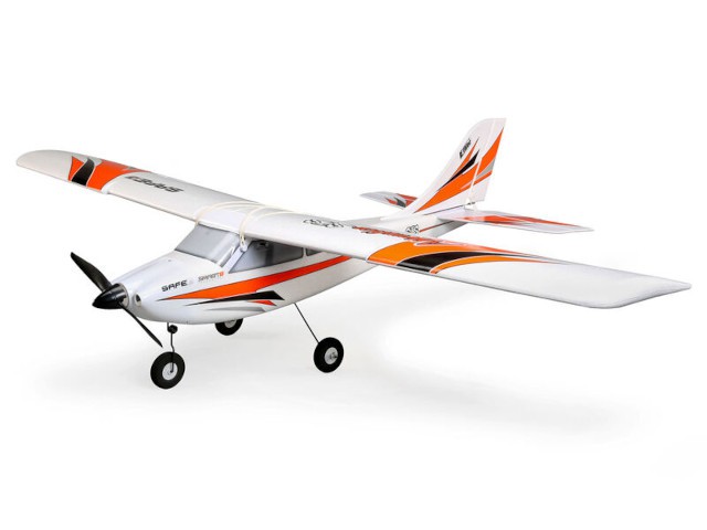
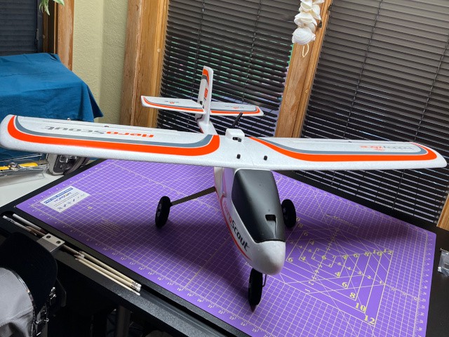
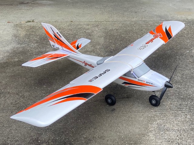
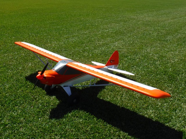
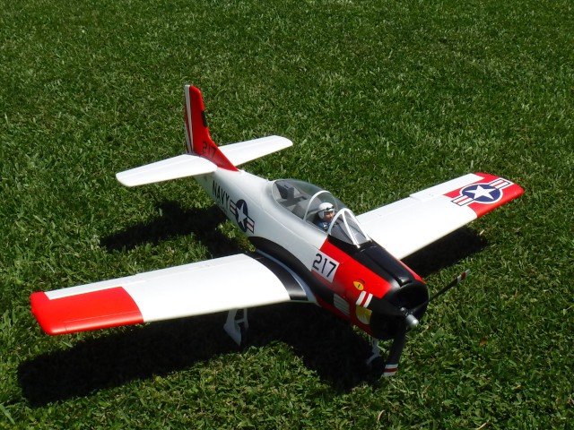
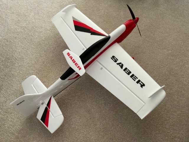
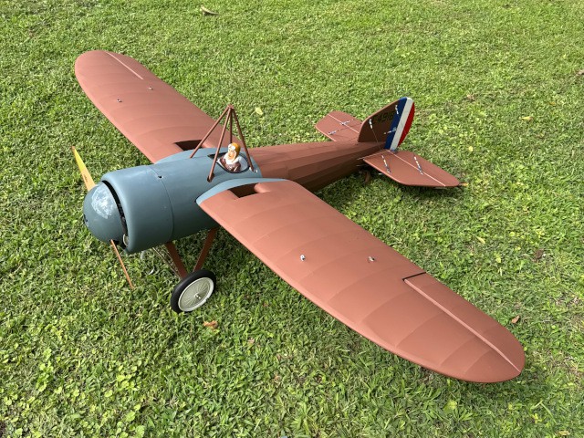
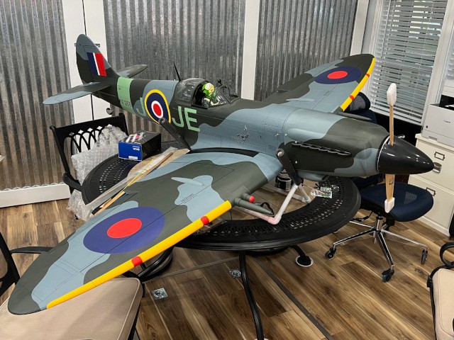
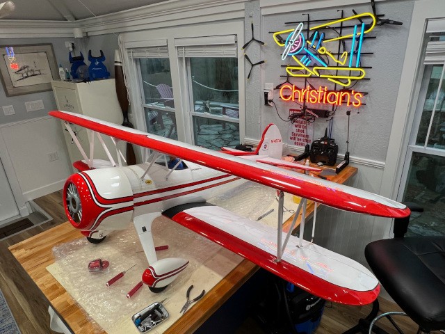
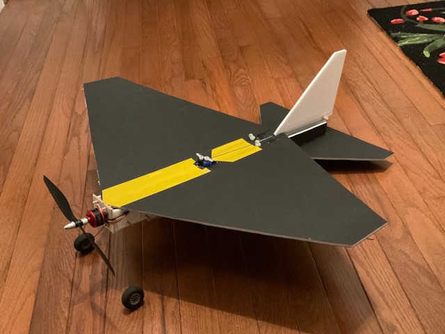
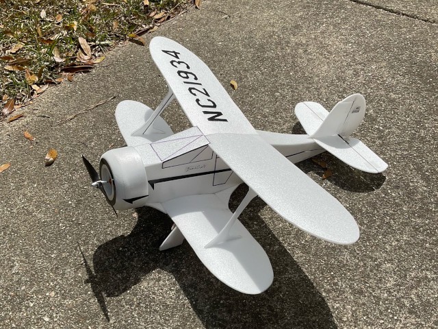
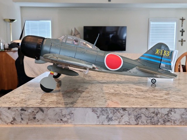
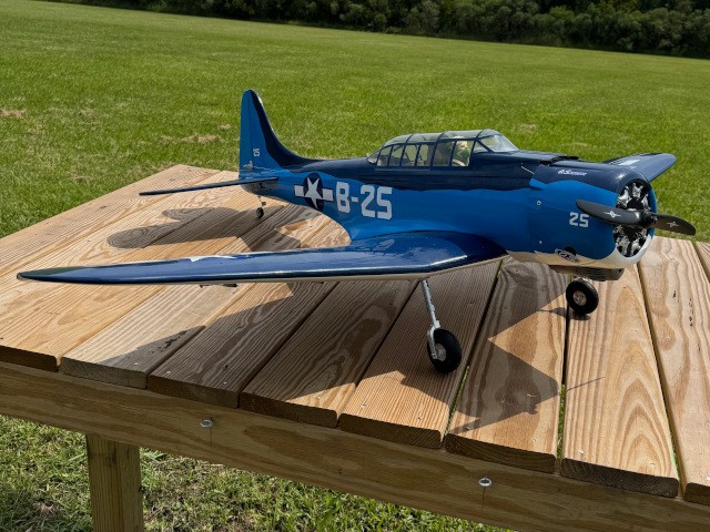
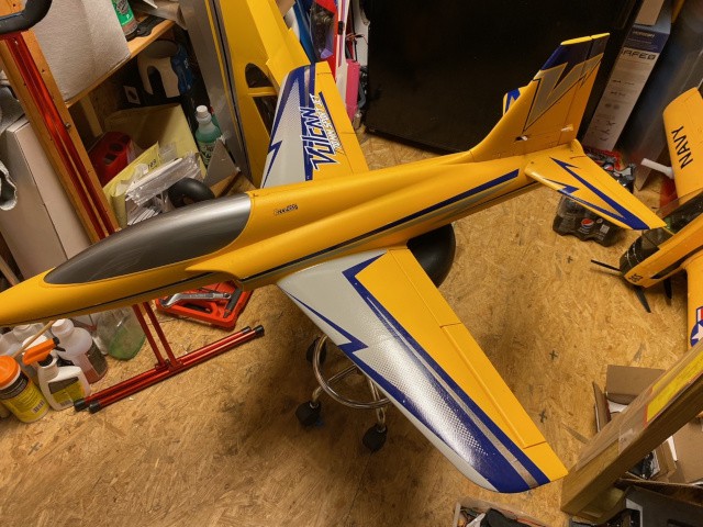
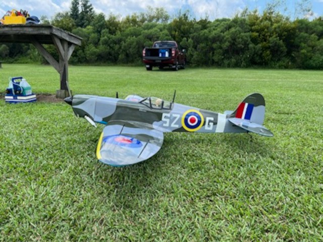
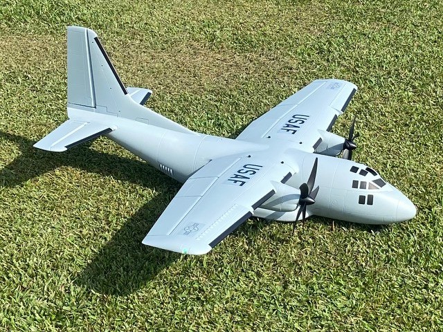
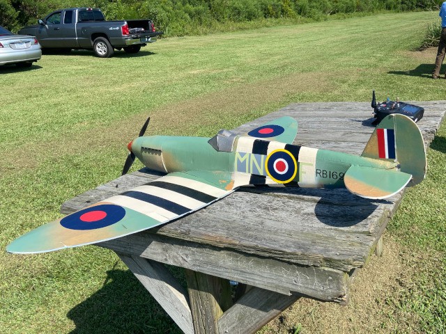
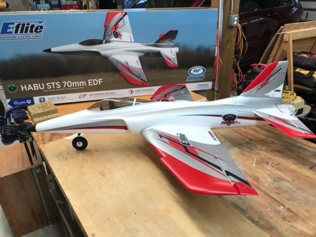
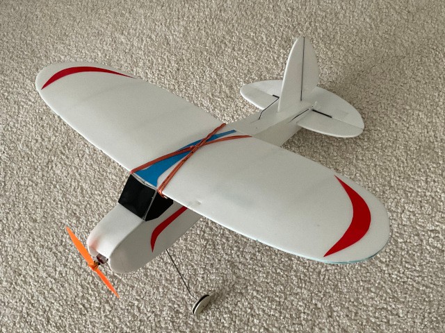
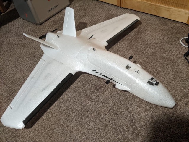
2025 Member Projects
Our members continue to build aircraft between flying and other club activities. Below are photographs of projects completed by Jim Shiels and Richard Boyd this year.
2024 Member Projects
Our members continue to build aircraft between flying and other club activities. Below are photographs of projects completed by Grant Dick, Jim Shiels, Richard Boyd, John Silva, and Mike Alexander this year.


2023 Member Projects
Our members continue to build aircraft between flying and other club activities. Below are photographs of projects completed by Jim Davis, Richard Boyd, Jim Shiels, Peter Fynn, Grant Dick, and Philip Garey this year.

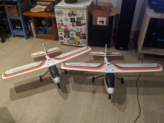
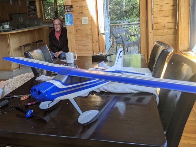
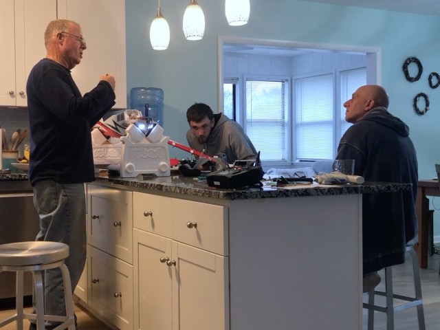
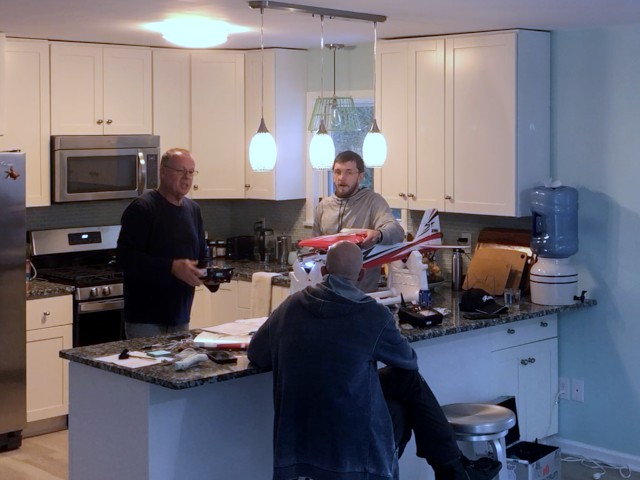
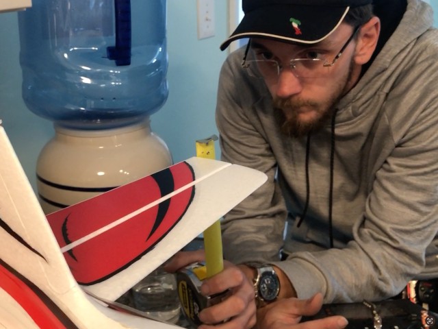
New Turbo Timber Evolution: 02/25/23
On a rainy February weekend Stephen Yanacek and Guy Marino visited with Grant Peacock for lunch and to assist him with setting up his new Turbo Timber Evolution.
The plane was deemed ready for flight by the end of the visit, but not before Grant's wife busted him for using her new sofa as an assembly table.


2022 Member Projects
Our members continue to build aircraft between flying and other club activities. Below are some photographs of the projects that Jim Shiels, Stephen Yanacek, Grant Peacock, Roberrt Yanacek, Charlie Doss, Peter Fynn, Richard Boyd, Philip Garey, and Mike Kirkpatrick completed this year.